C4FM stands for Continuous 4-level Frequency Modulation. (FM), and is the actual digital modulation of the radio signal used in System Fusion over VHF/UHF. Wires-X is the node linking/voip technology that allows nodes to link across the Internet.
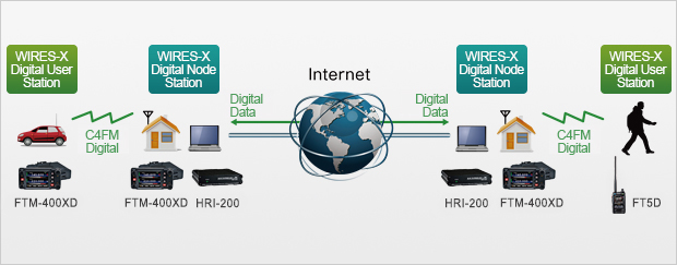
For WIRES-X, an amateur node station connecting to the Internet is used as the access point and connects the wireless communication to the Internet. Users’ stations can communicate with other amateur stations all over the world using a node within the radio wave range.
WIRES-X supports the C4FM digital and the clear and crisp voice technology enables high sound quality. By repeating C4FM digital data as it is via the Internet, users can enjoy clear voice communications even if they are thousands of miles away each other.
Utilizing the digital communication, the WIRES-X operation is simple, easy and user friendly. Varieties of the new functions as well as voice communications expands opportunities for enjoyment of ham station operation.
WIRES-X automatically connects to nodes and rooms via the Internet. No more need to verify connection IDs or transmit cumbersome DTMF connection codes.
Information about nodes and rooms is exchanged via C4FM Digital signaling. Thanks to automatic reconnection to the previous contact, all you need to do is press PTT and start talking. Easily search for new nodes and rooms, and initiate communication promptly when you find an ID that captures your interest.
Yaesu FT-70D, finding and saving Wires X rooms into memory
A repeater, in concept, is not really a complicated device. A repeater is an automatically controlled transmitter and receiver that simply transmits what the receiver hears simultaneously. Imagine having a receiver on one channel, and a high power transmitter on the other, and then holding the microphone of the transmitter in front of the speaker of the receiver. Now make the operation fully automatic. Any user that can be heard by the receiver has the effectiveness of the high power transmitter at his control.
In general, repeater systems are usually located in places of high elevation (on tall towers, on top of mountains or tall buildings) and are equipped with large and efficient antennas, extremely low loss feedlines, and a transmitter and receiver that is very durable, rated for continuous duty, and built to be as immune as possible to interference.
The end result? People using a repeater get much greater range from their radio equipment than would be possible talking from radio to radio. This is how an individual with a portable walkie-talkie (handheld) transceiver can communicate with people many miles away with good clarity.
Repeaters are used in police, fire and ambulance service communications (commonly called “Public Safety”), Commercial (Business) Communications, Federal, State and Local Government agencies, Emergency Communications, and by Amateur Radio Operators. Repeaters can be powered by the regular commercial power lines, or they can be connected to multiple sources of power, including batteries and/or generators for when commercial power is lost. Repeaters can be built that are extremely power efficient and may run exclusively from batteries; recharged by solar, wind or water power.
Simplex is point to point communications without the use of a repeater. Simplex operation utilizes the same frequency for receive and transmit, like a CB radio. I.E. Portable to Portable or Mobile to Mobile. The commercial 2-way world calls Simplex operation ‘Talk Around” because you are talking around the repeater, not through it.
There are such things as Simplex Repeaters. These machines listen on the frequency for activity, when it recognizes something it will begin to record that activity for a pre-determined time; usually 1 minute. A slang term for these is a “parrot repeater”. After the activity ceases or the time has expired, the unit will repeat what it has recorded. This method of communications is somewhat cumbersome over a conventional repeater; because you are forced to listen to what you said earlier in time and the channel usage is problematic as you never know when someone else is recording; however it should not be discounted as these types of systems can be very beneficial.
What is Duplex
The simple explanation of full duplex operation is like the telephone, where both people can talk at the same time. In contrast, a pair of handhelds operate in half-duplex mode because only one person can talk at a time. Since the ‘repeater’ listens and talks at the same time in relaying your message, it operates in full duplex mode.
How does a Repeater work
At first glance, a repeater might appear complicated, but if we take it apart, piece by piece, it’s really not really so difficult to understand. A basic repeater consists of several individual pieces that, when connected, form a functional system. Here’s a simple block diagram of a repeater:
The collection of the antenna, the feedline, the duplexer, and the interconnecting cables is frequently called the “antenna system”.
Antenna
Most repeaters use only one antenna. The antenna simultaneously serves both the transmit and receive RF (Radio Frequency) signals that are going in to and out of the repeater. It’s generally a high performance, durable, and very efficient antenna located as high on a tower or structure as we can get it. Antenna systems of this type can easily cost $500 or more, and that’s not including the feedline. On the other hand, when properly installed and maintaned they can last from 10 to 25 years.
Feedline
The feedline on most repeaters isn’t just a piece of standard coax cable, it’s what’s called Hardline. This stuff is more like a pipe with a center conductor than a cable. It’s hard to work with and very expensive. So why do we use it? Performance! The signal loss is much lower in hardline than in standard cable, so more power gets from the antenna to the receiver and weaker signals can be received. A hard rule is that once any percentage of a received signal is lost that you can’t get it back – ever.
Remember, the signal at a repeater site doesn’t just travel a few feet to an antenna like in a mobile rig. It may go hundreds of feet up the tower to the antenna. Just for fun check out the specs on a roll of coax some time and see how many dB of loss you’ll get from 200 feet of cable, and remember 3 dB is 1/2 of your power, and 10 dB is 90% of your power. Hardline also tends to be more durable than standard cable, which increases reliability and helps us minimize the financial expense, and the tower climbs to replace it.
Duplexer
This device serves a critical role in a repeater. To make a long story short, the duplexer separates and isolates the incoming signal from the outgoing and vice versa. Even though the repeaters input and output frequencies are different, the duplexer is still needed. Why? Have you ever been in a place where there’s lots of RF activity, and noticed the receive performance of your handheld radio degrades to some degree? This is called desensitization, or desense, and it’s a bad thing on a repeater. The receiver gets noisy or gets desensitized to the point of total deafness from the strong RF signals being radiated in its vicinity and confused about which signal it should receive.
The result is poor receive quality, or in extreme cases, complete lack of receive capability. Keep in mind that in this example, the radios are picking up radiated power from one another and that’s enough to cause trouble. Now imagine how much trouble there will be if you not only have the transmitter and receiver close together, but connect them to the same antenna!
Transmitting only a few hundred kHz away in frequency would blow away the input to the receiver if the equipment was simply connected together with a Tee. That’s where the duplexer comes in; it prevents the receiver and transmitter from ‘hearing’ one another by the isolation it provides. And the more isolation the better.
A duplexer is a device that is referred to by several different names like cavities or cans. A duplexer has the shape of tall canisters and is designed to pass a very, very narrow range of frequencies and to reject all others. There is some loss to the system because of the duplexer (called the “insertion loss”), however, the advantage of being able to use a single antenna and a single feedline usually outweighs the drawbacks.
Receiver
Receives the incoming signal. This receiver is generally a very sensitive and selective high performance one which helps weaker stations to be heard better by the repeater. It’s also where CTCSS (Continuous Tone Coded Squelch System) or “PL” decoding takes place. More on this later.
Transmitter
Most machines have a transmitter composed of two parts: an ‘exciter’ and a power amplifier. The exciter created low level RF energy on the proper frequency and then modulates it with the audio. The power amplifier stages simply boosts the level so the signal will travel further. Transmitters come in two types: intermittent duty and continuous duty. One that is rated for continuous duty is preferred.
The “Station”
The term “Station” is used to describe a stationary two way radio set; which includes the transmitter, receiver and sometimes the control circuitry. One example is the dispatch radio for a fire department. A ‘Repeater Station’ is a station designed to be used as a duplex repeater.
Controller
This is the brain of the repeater. It handles station identification (through either CW or voice), activates the transmitter at the appropriate times, controls the autopatch, and sometimes does many other things. Some machines also have a DVR (Digital Voice Recorder) for announcements and messages. The controller is a little computer that’s programmed and optimized to control a repeater.
The various models of controllers have different useful features like speed-dial for phone patches, a voice clock, facilities to control a remote base or linking, etc. The controller gives the repeater its ‘personality’. Whenever you’re using a repeater, you’re interacting with its controller. In the early days of repeaters the controller was a large chassis full of relays and timers. These days a controller is most often a microcomputer based unit.
What is a Phone Patch or Autopatch? AKA “The Patch”
Many repeaters have a feature that allows you to place a telephone call from your radio. Phone calls are generally restricted to the local calling area of the repeater to avoid long distance charges to the repeater’s sponsors. If in doubt, ask if the repeater has an open patch and how to access it.
When using the patch it is common courtesy to announce your intentions, e.g. “This is N3XZY on the patch”. This may help to prevent anyone from keying up while you are trying to use the function. In most areas when you are finished with the patch the accepted protocol is to announce it, e.g. “This is N3XZY clear the patch”.
DVR A DVR is a Digital Voice Recorder, or in modern terms a “voice mail” system for the repeater. Usually it’s an option that is installed into the controller.
Repeater Operation Operating using a repeater isn’t difficult. A good source of info is the ARRL Repeater Directory. It’s an inexpensive book with repeater listings all over the US. It contains frequency, offset and whether the repeater is + or – in shift (see “offset” below), whether or not it requires a PL tone, and other features (like an autopatch, or repeater-to-repeater linking).
What is Offset In order to listen and transmit at the same time, repeaters use two different frequencies. On the 2 meter ham band these frequencies are 600 kHz apart. As a general rule in the USA, if the output frequency (transmit) of the repeater is below 147 MHz then the input frequency (listening) is 600 kHz lower. This is referred to as a negative offset. If the output is 147 MHz or above then the input is 600 kHz above. This is referred to as a positive offset. However in any given area the offset rules can be different.
Virtually all ham radios sold today set the offset once you have chosen the operating frequency. As an example one repeater output is 145.270 MHz. The input, or the frequency it listens on is 144.670 MHz (600 kHz below). If you have your radio tuned to 145.270 MHz with the offset enabled, when you push the PTT switch (Push-To-Talk) your radio automatically transmits on 144.670 MHz. When you release the PTT to listen, the radio reverts back to 145.270 MHz to listen on the repeater’s output frequency.
Standard Repeater Input/Output Offsets
Band
Offset
6 meters (50-54 MHz)
No real nationwide standard, it varies widely. Most common are -500 kHz, -600 kHz or -1.0 MHz
2 meters (144-148 MHz)
Up and down 600 kHz, depends on frequency
1.25 meters (222-224 MHz, also called “220”)
Down 1.6 MHz
70 cm (440 MHz, also called “UHF”)
Up or down 5 MHz, depends on local area usage
33 cm (900 MHz)
-25 MHz
23 cm (1200 MHz)
-20 MHz
Note: There are exceptions to the above so check local repeater listings.
Why do Repeaters use an Offset To use a repeater a user station must use a different transmit frequency than receive frequency. This is a form of duplex, or two frequency operation. It is known as half-duplex as you do not receive and transmit at the same time but normally use the push-to-talk button on your microphone to switch between the two.
Most repeater installations use the same antenna for transmit and receive. Without having an offset the repeater would simply hear itself when it was transmitting on the same frequency it was listening on. Even with the offset, the two frequencies are close enough that antenna system isolation is required. Again, this isolation is afforded by the duplexer.
What is Carrier Access, Tone Squelch, CTCSS or a PL Tone Carrier Access, or Carrier Squelch means that the repeater is looking for a carrier on the receiver frequency to open the squelch. A circuit called a Carrier Operated Switch (COS) or Carrier Operated Relay (COR) senses the squelch opening, and tells the repeater that there is a carrier on the input. The controller keys the transmitter, thereby repeating the signal.
Continuous Tone Coded Squelch System, or CTCSS, is a radio communications industry standard signaling scheme. It provides an electronic means of allowing a repeater to respond only to stations that encode or send a very precise audio tone at a very low level superimosed on the transmitter along with the microphone audio. The CTCSS system is used to prevent the repeater receiver from responding to unwanted signals or interference (it’s looking for both the carrier and the tone before the signal is considered as valid).
If a repeater is “in tone mode” that means it requires a CTCSS tone to activate the repeater. If it is in “Carrier mode” then it is ignoring the CTCSS decoder, if there is one. Modern repeater controllers offer a way to switch back and forth, even automatically, between the two modes. Originally there were 32 standard tones, now there are 37.
Some manufacturers offer more, but most repeaters use one of the original 32 so as to allow the older radios to use the system. Aftermarket tone generators from several differnet manufacturers allow any station to be set up to transmit a CTCSS tone. The tones are in the 67-250 Hz range and are called sub-audible, because they’re below the normal voice audio range of 300-3000 Hz. This doesn’t mean you can’t or won’t hear them; they can be quite noticeable depending on the radio you’re using.
PL, an acronym for Private Line, is Motorola’s proprietary name for CTCSS. General Electric uses the name “Channel Guard” or CG for the same system. Other names, such as Call Guard, Quiet Channel or Quiet Tone are used by other manufacturers.
In days of old, repeaters that used PL were considered to be closed or private. This is no longer the case as tone operation has become more the rule instead of the exception. Uninformed people use CTCSS to “solve” interference problems. It doesn’t. It just covers them up, or hides them. The unwanted signal is still on the repeater input, the tone decoder simply prevents the repeater from making it obvious.
Of course, everything these days is digital. A later system called Digital Coded Squelch (DCS) uses 85 different sub-audible digital bit streams. Motorola uses the name Digital Private Line, or DPL for this. Other manufacturers use different names. DPL is gaining in popularity since more radios now come with it as a standard feature.
How do you call someone on an Amateur Repeater? First, listen to make sure that the repeater is not already in use. Then listen some more. If you are a new ham that has never used a repater before it might pay to listen for a week or so and see what goes on, who seems to be the “regular users”, and if you know any of them, perhaps from the local ham club meeting.
When you are satisfied that the repeater is not in use, begin with the callsign of the station you are trying to contact followed by your callsign. e.g. “W3ABC this is N3XYZ”. If you don’t establish contact with the station you are looking for, wait a minute or two and repeat your call.
If you are just announcing your presence on the repeater it is helpful to others that may be listening if you identify the repeater you are using. e.g. “This is N3XYZ listening on 6-2-5”. This allows people that are listening on radios that scan several repeaters to identify which repeater you are using (and therefore which microphone to pick up to answer you).
If the repeater you are using is a busy repeater you may consider moving to a simplex frequency (transmit and receive on the same frequency), once you have made contact with the station you were calling. Repeaters are designed to facilitate communications between stations that normally wouldn’t be able to communicate because of terrain or power limitations. If you can maintain your conversation without using the repeater, going “simplex” will leave the repeater free for other stations to use.
Repeater Etiquette The first and most important rule is LISTEN FIRST. Few things are more annoying than someone that “keys up” in the middle of another conversation without first checking to make sure the repeater is free. Saying that your volume control was down too low and you didn’t hear any conversation is no excuse – it just says that you didn’t chack your own station before you used it. If the repeater is in use, wait for a pause in the conversation and simply announce your callsign and wait for one of the other stations to acknowledge your call.
When you are using the repeater leave a couple of seconds between exchanges to allow other stations to join in or make a quick call. Most repeaters have a “Courtesy Tone” that will help in determining how long to pause. The courtesy tone serves two purposes. Repeaters have a time out function that will shut down the transmitter if the repeater is held on for a preset length of time (normally three or four minutes). This ensures that if someone’s transmitter is stuck on for any reason, it won’t hold the repeater’s transmitter on indefinitely.
When a ham is talking and releases the push-to-talk switch on their radio, the controller in the repeater detects the loss of carrier and resets the time-out timer. Many of the modern computerized controllers allow the owner to program a “beep” to indicate that the timer is reset. This beep is called the courtesy beep, or the courtesy tone.
If you wait until you hear this beep (normally a couple of seconds) before you respond, you can be sure that you are pausing a suitable length of time. After you hear the beep, the repeater’s transmitter will stay on for a few more seconds before turning off. This is referred to as the “carrier delay”, or the “hang in timer”. The length of the delay will vary from repeater to repeater but the average is about 2 or 3 seconds. You don’t have to wait for the transmitter to drop off the air before keying up again, but you should make sure that you hear the courtesy tone before going ahead.
Note: If you don’t wait for the beep the time-out timer to may not reset. Some repeater clubs have a rule that if you time-out the repeater you get to buy a round of coffee at the next ham club meeting.
What is “Doubling” ? When two stations try to talk at the same time the signals mix in the repeater’s receiver and results in a buzzing sound or squeal. When you are involved in a roundtable discussion with several other stations it is always best to pass off to a specific person rather than leave it up it the air. e.g. “W3ABC to take it, this is N3XYZ” or “Do you have any comments Fred?, this is N3XYZ”. Failing to do so is an invitation to chaos and confusion.
It is for this very reason that when groups hold scheduled Nets (network of hams meeting on air at a predetermined time), they assign a Net Control station. The Net Controls job is to make sure there is an orderly exchange and that all stations get a chance to speak. Listen to a local net and you will get an idea of the format and how the Net Control juggles the various stations and traffic.
It’s a job almost anyone can handle, but as you will discover, some are much better at it than others. And if you try your hand at being Net Control for a night, you will discover just how hard it can be! (and you will gain a lot of respect for those that have the knack to do it and make it sound easy). A well run net is both informative and entertaining!
What is a Control Operator? The Part 97 of the FCC Rules requires all stations in the Amateur Service that are capable of operating unattended must be monitored for proper operation while in the unattended mode. This monitoring function is accomplished by a control operator. The Control Op can be the licensee of the station or anyone he or she chooses. In many cases, he or she also ends up being the person that answers questions about the repeater.
What is White Noise? White noise is a term used to describe a spectrum of broad band noise generated in a receiver’s detector and sampled to control the receiver’s squelch. When you open the squelch control and hear the rushing noise from the speaker, this is white noise. When the receiver is in carrier squelch mode the squelch circuit uses the presence of that noise to decide that the signal has gone away and it should mute the receiver speaker.
When the receiver is in tone squelch mode it uses the abscence of the tone AND the presense of the noise to indicate loss of signal. The “squelch tail” is that burst of white noise that you hear that starts when someone unkeys and ends when the squelch circuit actually mutes the receiver audio (some people mistakenly use the term to refer to the carrier delay mentioned above).
I hope this article has explained the Repeater in enough detail that you understand what it is and how to use it. If there is any part of this article that seems vague or confusing, please write me and I’ll do my best to explain it better.
The word “grounding” — meaning a connection to the Earth — is casually applied to so many different purposes in Amateur Radio, it’s no wonder there are many opinions and misconceptions about it. “Bonding” is a less familiar term to most amateurs. In the electrical sense, bonding simply means “to connect together” so that voltage differences between pieces of equipment are minimized.
Why Are Grounding and Bonding Important?
There are three needs we are trying to satisfy:
• AC safety: protect against shock hazards from ac-powered equipment by providing a safe path for current when a fault occurs in wiring or insulation.
• Lightning protection: keep all equipment at the same voltage during transients and surges from lightning and dissipate the lightning’s charge in the Earth, routing it away from equipment.
• RF management: prevent unwanted RF currents and voltages from disrupting the normal functions of equipment (also known as RF interference or RFI).
Why Is “Grounding” So Complicated?
The very word — grounding — means a lot of different things depending on who you’re talking to and what you’re talking about. Isn’t grounding just connecting equipment to the Earth? That is certainly one definition of grounding.
The British use the terms “earthing” and “protective earth conductor” which are more exact references to what the connection is for. But the layer of soil and rock at the Earth’s surface is not a magic zero-voltage point into which we can pour any amount of electric charge where it safely disappears! The current’s strength and frequency, soil characteristics, whether it is wet or dry, the length of the path to the Earth connection and through the soil — all of these affect what our equipment experiences at the “ground” connection.